Practical Engineering Considerations for CIP Systems
Why CIP Matters in Modern Facilities
Effective Clean-in-place (CIP) processes can be taken for granted but are the backbone of repeatable and safe food production.
When CIP is working as intended, production scheduling is easier, operational costs are lower, and confidence in the product quality is high.
When confidence is shaken in a CIP system a site can experience production delays and higher operational costs.
CIP is like safety. When it is performing well few people notice but when an incident occurs suddenly it can become a focal point and people wonder why it wasn’t better designed.
CIP Fundamentals
CIP design at its core has been unchanged for many years. Four key elements are required for a successful CIP: Time, Temperature, Chemistry, and Mechanical Action.
All four need to work in harmony for successful cleaning. Lack of one can be overcompensated by the others but only to an extent. No amount of soaking of a stain is a substitute for elbow grease, for example.
Most everyone has their own CIP system in their house – the dishwasher. A dishwasher utilizes the same key principles an industrial CIP system does. Think of how a dishwasher works. Can it work effectively while missing one of the key elements?
CIP Industry Trends
At their core, CIP systems are the same as they always have been but with recent developments in valve technology, controls, automation, and equipment, much more repeatable systems can be designed that use less water, time, and chemicals to achieve good results. Some examples of recent innovations around CIP include:
Automation with Single-seat and mix-proof valves – many CIP designs now are using single-seat and mix-proof valves as the automated valves in the CIP circuits both out at the process and for the CIP system itself. These valves do not have internal harborage points and can be cleaned through without disassembly. Mix-proof valves can have both CIP and product fluids passing through them simultaneously which can allow for higher production uptime on shared processes. Use of single-seat and mix-proof valves with position feedback provides peace of mind to ensure CIP fluid is going where it is supposed to. They also limit or can even eliminate operators needing to interact with flow panels.
Many sites now use a premixed formulated caustic which reduces the amount of chemical handling by operators on site. Instead of diluting caustic manually or handling caustic in multiple tanks, a single tank or drums can be used to limit operator exposure and risk of dosing errors.
No-rinse sanitizers are highly utilized at sites and present an excellent way to provide an additional layer of protection at the end of a CIP circuit. Dosing these sanitizers is critical as many systems can over or under dose sanitizer without the site tracking the dosage or timing.
Spray balls – innovations with spray balls include rotary and jet spray balls that perform effectively while using less water. Note that rotary and jet spray balls do require higher pressure then their static counterparts.
Twin screw pumps – these pumps can be utilized both for the normal process and CIP return. They will run at a low speed during normal production and then can ramp up to meet the flow requirements for a CIP process. They can eliminate needing extra equipment or flow panels/valves.
CIP Validation Criteria
A CIP system can be designed perfectly but unless key parameters are being tracked and recorded how would anyone know that it’s cleaning effectively? Key parameters that should be tracked and recorded include: flow (both supply and return), conductivity, temperature, duration,
Each tracked parameter corresponds to the four key elements. Flow directly relates to mechanical action both for cleaning of pipes and equipment. For cleaning piping, a typical best practice target velocity is a minimum of 5 feet per second. For standard OD tubing the below table captures typical minimum GPM targets.
| Tube OD (in) | Tube ID (in) | GPM Target for 5FPS |
| 0.5 | 0.37 | 1.7 |
| 0.75 | 0.62 | 4.7 |
| 1 | 0.87 | 9.3 |
| 1.5 | 1.37 | 23.0 |
| 2 | 1.87 | 42.8 |
| 2.5 | 2.37 | 68.8 |
| 3 | 2.87 | 100.8 |
| 4 | 3.834 | 179.9 |
| 6 | 5.782 | 409.2 |
For tank and vessel cleaning, the flow requirement will be the minimum flow required by the spray ball(s).
Conductivity is the measurement of the fluid to conduct electrical current. Conductivity is directly related to the amount of chemical in the CIP solution (typically caustic, acid, or sanitizer). Tracking conductivity on the CIP return is important for repeatable cleaning and can be used to identify leaks or issues with the chemical dosing systems.
Tracking temperature on the supply and return is important to ensure the process is being cleaned at the desired temperature. Caustic cleaning is most effective between 140-180F so ensuring the temperature is within the target range is critical to ensure adequate cleaning.
Duration is self-explanatory but it is important to capture the length of the overall CIP process and each sub step. Typically, all other parameters need to be at their desired set points for the timer for a CIP circuit to begin. Trending the time to reach the setpoints and the number of times the CIP is interrupted can be very helpful to troubleshoot issues that delay a CIP cycle from completing.
Additional tools that are beneficial for CIP validation are monitoring the tank levels of any equipment being cleaned and positions of valves and flow panels in the CIP circuit.
Common CIP Pitfalls and Their Root Causes
Troubleshooting CIP systems can be intimidating. Without proper data collection it can be impossible to identify the root cause of CIP issues. Establishing CIP validation criteria and installing reliable instrumentation to track the items previously mentioned is the first and most important step to identify any CIP design issues.
Once the data for the four key elements is being tracked a site can quickly identify if any of the elements are missing and which need to be adjusted.
Some examples of CIP issues and potential solutions are captured below:
Leaks – leaking is inevitable in some CIP systems with open processes, but the leaks can be minimized to avoid excessive chemical/water loss and to ensure the system can meet its setpoints quickly. Tank manway gaskets should be regularly inspected and replaced to ensure tight seals. Additionally, any flow panels or hose connections should be regularly inspected for leaks. Newer tools such as spray deflectors by Sanimatic can reduce loss of CIP fluid from open vents on tanks:
Significantly manual procedures and HMI interfaces which allow for too much operator tweaking can also cause inconsistency across CIP’s. Allowing operators to control CIP parameters such as pump VFD speeds is a recipe for inconsistency or flooding of process vessels during CIP. Utilizing automation with well defined and repeatable set-points allows for repeatable results in CIP.
A very common issue is a misalignment between supply and return flow on a CIP circuit. The CIP return pump must be capable of the maximum flow it will see from the CIP supply pump. Typically a positive displacement process pump cannot keep up with a CIP system. Either a twin screw or a supplemental centrifugal pump is required to keep up.
Chemical dosing systems are often neglected and poorly designed. Dosing small amounts of fluid, especially sanitizer, requires specialized pumps and instrumentation to ensure repeatability and accuracy. Dosing based on measured flow is more accurate than dosing on time. Also, instrumentation can be utilized to identify when chemical levels are low to avoid stalling a CIP circuit due to lack of chemical.
Tank Cleaning
Tank cleaning is frequently a source of pain and confusion. Often tanks are cleaned with a brute force approach with static spray balls. There’s nothing wrong with this approach but often the CIP return pump cannot keep up with the supply, and the site operators will slow down the flow into the tank to avoid the tank from bath tubbing or flooding. Tank bottoms cannot be well cleaned without being exposed and if the tank is flooded the spray balls cannot achieve the mechanical action required. Spray ball companies typically have handy tables for the effective cleaning radii of their spray balls. Spray ball design should ensure that the distance from the spray ball to the furthest part of the tank is within these radii. Also if a vessel has an agitator or other obstruction, multiple spray balls are required to clean around the obstructions.
In retrofit installations or ones where a site wants to limit flow rates, rotary or jet spray devices can be used. These devices have motion incorporated that allow them to clean more effectively with less water. Two key caveats should be considered. Although these devices require less flow for equivalent cleaning to a static spray ball, they do require higher pressure, and they have a reduced service life. A typical static spray ball requires ~25 psi but a rotary often needs 44 psi and a jet can need as much as 70 psi. These devices should be inspected regularly because due to their rotating parts they have a set service life and will not perform if the bearings fail.
Pipe Cleaning
As mentioned earlier, the typical target velocity for good line cleaning is 5 feet per second but that is just a minimum. For heavy soils or long durations between cleaning, velocities up to 10 feet per second may be needed.
The first step to ensuring good line cleaning is to have accurate, repeatable flow measurement devices in both the supply and return piping of a CIP system. Why both supply and return? Often there is an atmospheric break in a CIP system which can cause the supply and return flows to be mismatched at times. Also, if there are system leaks a flowmeter can identify gaps between the supply and return flows.
The cleaning circuit selection is important to ensure these minimum 5 fps targets can be reached for all piping in a CIP system. As shown in the table earlier, the flow requirement for cleaning larger diameter pipes goes up dramatically as the pipes get bigger. Cleaning a 3” pipe requires more than double the flowrate vs cleaning a 2”. Many sites have piping systems with multiple diameter pipes in a given CIP circuit. Trying to force 100 gpm through a 1” pipe to clean the 3” pipe on the same circuit is not practical.
Establishing multiple smaller circuits to clean different pipe diameters can be one way to ensure adequate cleaning on all pipes in a circuit. Also installing jumpers at small diameter pipes or at flow restrictions such as at process pumps can also be a way to ensure good velocity in all sections of a CIP circuit. Lastly, matching pipe diameters in a process, even if there’s not a specific process need to do so, can be beneficial for good cleaning.
A Typical CIP Sequence
No two processes or sites are the same and the same is true of CIP sequences and setpoints. Many different considerations will go into determining CIP sequences, timing, and set points. Ultimately the sequence should be designed to be repeatable and to consistently meet the validation criteria while limiting time, chemical, and water usage. A typical sequence is shown below as an example:
- Water Flush
- Hot rinse
- Caustic Wash
- Intermediate Rinse
- Acid Wash (optional, can be used to neutralize residual caustic and to remove any scale from hard water or the process. Can also re-passivate surfaces)
- Water Rinse
- Sanitizer (no rinse sanitizers are common)
- Air blow
CIP Skid Design Considerations
The most common CIP system consists of a single tank, pump, and heat exchanger (or jacketed tank). The size and complexity of the system to be cleaned should govern which type of CIP system is most appropriate for the site. A multiple tank system is superior to a single tank system in many ways but may not be practical due to cost or space constraints.
A single tank system offers benefits of being low in cost and footprint and has less complexity and failure points since all the CIP fluid is processed in the same tank. Also, a single tank system can be mobilized for smaller processes to be used on demand.
However, a single tank system generally needs to dump its contents to drain between each sequence in the CIP which requires significant water and chemical and it also needs to be reheated each time if it does not have an external hot water supply.
A multiple tank system can be configured multiple ways but typically has dedicated rinse tanks and a dedicated caustic wash tank. If multiple rinse tanks are included, often the final rinse of one circuit can be recovered and used as the initial rinse for the next circuit. Having dedicated tanks allows staging of the tanks to occur and be ready to go within a CIP circuit which can dramatically reduce CIP time and can stabilize steam consumption.
Including spray balls to clean the CIP tanks themselves is also a best practice as well as having robust instrumentation including tank level and valve position feedback for troubleshooting.
CIP Pumps and Process Pumps
Not all pumps are created equal. A rotary lobe pump may be great for gently pumping yogurt but that does not mean it can meet CIP flow requirements. As mentioned previously, twin screw pumps are seeing increased utilization in modern food facilities as they can be used for both normal production and CIP but upgrading an existing site to twin screw pumps may not be cost effective and twin-screw pumps are not appropriate for all processes.
A self-priming sanitary centrifugal pump is an excellent choice for CIP return. It will perform better at the discharge of a tank when it sees air due to the tank being nearly empty during CIP. A self-priming design includes an inlet screw that reduces risk of cavitation and extends the pump life. Careful consideration should be given to the design of the pump to ensure it meets and exceeds the maximum flow rate required for cleaning the tank or pipes in the CIP circuit.
VFDs for both supply and return are a great way to
Historically, rotary lobe pumps needed to be fully disassembled and then behaved as a “wide spot in the line” during a CIP, with an external centrifugal pump providing the higher flow capacity required for good line cleaning. However, with newer innovations in rotary lobe pump design, new designs allow for the pump to stay fully assembled during CIP as long as considerations for flow are taken. There are multiple ways to ensure good cleaning through lines and rotary lobe pumps. The simplest is a manual jumper that is installed during CIP to bypass around the pump so flow splits between the pump and the bypass. However, this step is manual and can be forgotten or not performed consistently. A more modern design concept is the use of a sanitary single seat mixing valve that returns the pump discharge to the suction so the bypass around the pump can be throttled to achieve good line and pump cleaning.
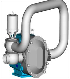
Image credit SPX
Steam Considerations for CIP
CIP processes are energy hogs due to the large amount of hot water they require. For many sites, the steam usage during CIP is one of the highest demands of any process. Often a CIP system is designed to target a temperature setpoint for a rinse or caustic wash and the controls allow the steam control valve to go wide open to try and meet the setpoint. This type of operation can cause unintended consequences as the steam header can suddenly drop in pressure as the CIP system calls for steam.
Many facilities utilize fire tube boilers which can require time to adjust to steam demand changes. Often the steam consumption of a CIP system is enough to drop the header pressure down and drive a boiler to high fire to compensate. Ultimately this can result in a boiler alternating between high and low fire which can not only cause process upsets but can also shorten the life of a boiler.
Multiple methods can be utilized to reduce the impact of the sudden steam demand of a CIP system. Use of a multi-tank CIP system can dampen out the steam demand if dedicated tanks are utilized for hot rinses as they can be gradually staged while other parts of the CIP circuit are running.
Also, use of a dedicated hot water system at the site can be a great benefit to reduce steam peaks and valleys. If a large hot water tank is maintained, the steam demand to make up the tank will be more of a consistent demand vs a spike that a sudden CIP wash can cause. Lastly use of water tube boilers vs fire tube boilers can be beneficial as they have less water in them for a given boiler and can therefore react to steam demand changes more quickly.
Final Thoughts: Engineering Ownership of Cleaning Reliability
CIP at a production site is not only everyone’s responsibility, but it also becomes everyone’s problem when it is not working effectively. Nobody wants to hear that their product is being recalled or that someone has gotten sick from their product.
Ensuring robust CIP validation provides peace of mind so that personnel at facilities can focus on product quality and innovation. Use of robust instrumentation, modern CIP practices, and data recording are great ways to ensure CIP is effective and repeatable every time.
If you’re looking to strengthen your CIP validation framework or need guidance tailoring best practices to your facility, we’re here to help.
Contact us today to schedule a consultation.
